
DF - 1071 DIRECTION FINDING ANTENNA
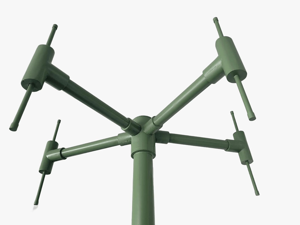


The DF – 1071 model DF antenna was developed for wide-band direction finding applications and consists of three main parts:
1. Upper Layer: Receives in the frequency range of 100 MHz – 350 MHz.
2.Middle Layer: Receives in the frequency range of 350 MHz – 1 GHz.
3. Switch Layer: It consists of switch circuits that perform the switching function between antennas.
The DF – 1071 antenna has a 5-segment structure and offers a total of 5 outputs.
Frequency Bands:
Band 1: 100 – 350 MHz
Band 2: 350 – 1000 MHz
Impedance: 50 Ω
VSWR: 2:1
Output: RG 58 cable, 10× BNC male connector
Polarization: Vertical
Power: 15 V DC, <150 mA, <2.25 W
2/1 SWITCH BOX
The 2/1 Switch Box is a switching box that can accommodate 10 antenna inputs. Thanks to its 2/1 switch structure, signals are routed to five output ports by selecting between the input antennas. This allows signals received from different antennas to be evaluated simultaneously or separately. This structure is designed for use in wide-band antenna measurements, direction finding (DF) applications, and multiple antenna tests.


VHF MARINE ANTENNA
Frequency Range: 150MHz-170MHz
RF Output Power: 100W
Gain: 3Dbi
Polarization: Vertical
Dispersion Model: Equal distribution in all directions
UHF MARINE ANTENNA
Frequency range: 350MHz-470MHz
RF Output Power: 100W
Gain: 3Dbi
Polarization: Vertical
Dispersion Model: Equal distribution in all directions

İletişim
Kirazlıdere Mah. Eski Ankara Cad. İdari Bina A-1 Blok No:4A-1, Çekmeköy/İstanbul -TÜRKİYE
(Recep Tayyip Erdoğan Üniversitesi & Türk-Alman Üniversitesi Teknoloji Geliştirme Bölgesi Çekmeköy Kampüsü)